If you own a Jeep JK Wrangler and you are serious about off-roading, upgrading to a long arm suspension kit is one of the single biggest improvements you can make. Long arms reduce axle wrap, increase articulation, and deliver a smoother ride on and off the trail. In this guide, Spence from Core 4x4 walks through a complete long arm kit installation on the shop JK — from bracket prep and welding all the way through control arm measuring, torque specs, and a final pinion-angle check.
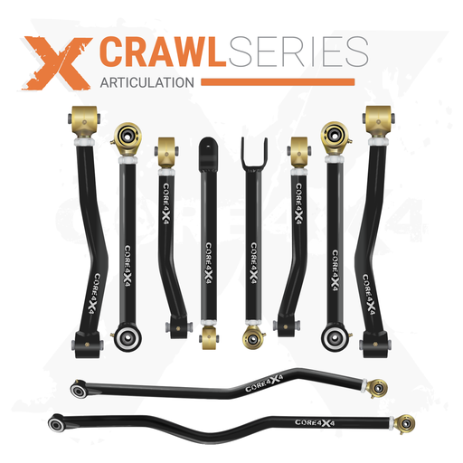
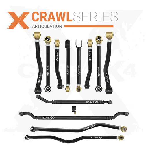
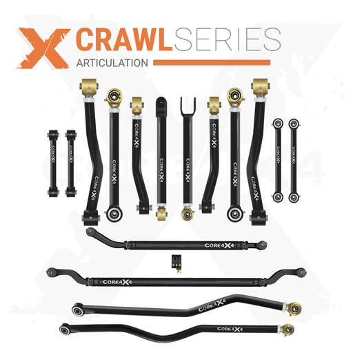
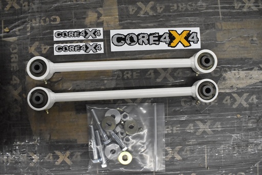
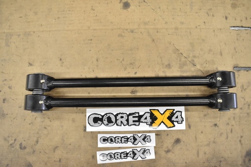
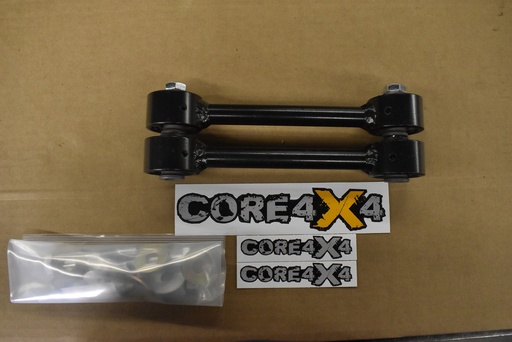
This install uses the Core 4x4 Crawl Series long arm kit with double-adjustable Johnny Joints on both ends of every arm. Whether you are tackling your first weld-on suspension project or upgrading from stock short arms, this post covers everything you need to know to get it done right.
Fitment: 2007–2018 Jeep Wrangler JK / JKU (2-door and 4-door)

What You Need Before You Start
This is a weld-on kit, so plan for a full weekend if it is your first time. Spence knocked it out over two days — bracket welding on day one, arms and reassembly on day two. Here is the short list of tools and supplies beyond the usual wrenches and sockets:
- MIG welder — you will be doing overhead welding on the frame, so practice if you are not comfortable with that position
- Weld-through primer — zinc-based for maximum corrosion resistance (recommended for salt-belt states), or copper-based for easier welding in milder climates
- Angle grinder with flap disc and wire wheel — for paint removal and weld cleanup
- Scribe or etching tool — to mark bracket position on the frame before grinding
- C-clamps — to pull rear brackets tight against the frame before welding
- Torque wrench (ft-lb range up to 250)
- 9/16″ drill bit — for the rear upper control arm frame mount
Step 1: Prime the Brackets
Before you touch the Jeep, get your weld-through primer on the bracket contact surfaces. The zinc-based primer Core 4x4 recommends runs about $40 a can, and one can will barely cover all four brackets plus the frame weld areas. Spray both the bracket-to-frame surfaces and the frame-side weld zones so everything can dry while you do your prep work.
Pro tip: If you have an extra set of brackets (or bare uncoated ones), use those for your mockup and measurement step so the primed set can dry undisturbed.
Step 2: Mock Up & Prep the Frame

Each front bracket lines up with a single factory hole on the back side of the lower control arm mount. Hold the bracket in place and use a scribe to mark the frame so you know exactly where to grind. Remove the bracket, then grind off all the paint, undercoating, and surface rust inside those marks. Clean metal is essential — paint and primer contamination will wreck your welds.
For the rear brackets, you will follow the factory welds where the rear portion of the frame overlaps the midsection, as well as the cross member. The rear brackets sandwich the frame, so use a C-clamp to pull them tight before you tack anything.
Drop the Exhaust (Optional but Recommended)
On the JK, the exhaust runs close to the rear driver-side bracket location. Disconnecting it at the front two junctures and dropping it off the hangers gives you much better grinder and welder access. Spence called the rear driver bracket “probably the best welds on the Jeep” after having the extra room, so the 20 minutes of exhaust work pays off.
Step 3: Weld the Brackets

Orientation is straightforward: the front brackets key off that single factory bolt hole; a small triangular gusset piece from the kit fills in one corner. Fully weld every seam you can reach. Spence likes to disperse heat by laying a bead on one bracket, then jumping to a different corner before coming back — this keeps any single bracket from warping.
After all four brackets are welded, hit every weld with a wire brush to remove mill scale (it will flake and rust if you skip this), then apply a coat or two of paint. Let everything dry overnight before mounting the arms.
| Bracket Welding Tips | Why It Matters |
|---|---|
| Grind all paint off weld zones | Clean metal = clean welds; paint causes porosity and weak fusion |
| Use weld-through zinc primer | Protects the frame-to-bracket interface where you cannot paint after welding |
| Do NOT weld inside control arm mounts | Welding inside the box can pull the tabs together, making arm installation extremely difficult |
| Disperse heat across all four brackets | Prevents warping and allows each bead to cool before the next pass |
| Wire-brush every weld before painting | Removes mill scale that will flake and cause rust |
Step 4: Measure & Install the Front Control Arms

With the brackets painted and dry, bolt the exhaust back up and start on the front end. On this particular JK — running 4.5-inch coils and Rock Jock 70 axles with built-in pinion correction — Spence started with these measurements:
| Front Arms | Starting Length (Eye to Eye) |
|---|---|
| Lower Control Arms | ~29″ (about ½″ stretch over stock) |
| Upper Control Arms | ~26″ |
Your measurements may differ depending on your lift height, axles, and coils. These are starting points.
When setting the length on a double-threaded arm with a bend (like the upper fronts), line the bend up in plane with the arm so both Johnny Joint mounting faces are parallel. This makes your eye-to-eye measurement accurate instead of trying to split the difference between an inside and outside measurement.
Install the uppers first while you have the room, then the lowers. The kit includes a nut tab for the upper front control arm frame mount. Once both sides are set to the same length, torque everything down.
Front Orientation Note
The upper control arm bend is an inward bend for frame clearance. When you tighten the jam nuts, orient the bend away from the frame so you get maximum clearance during droop and flex.
Step 5: Body Mount Relocation

Before the rear arms go in, handle the body mount. The kit includes a relocation plate that shifts the body mount over about two inches to clear the new rear upper arm bracket. Bolt the plate to the factory body mount hole first, then install the factory body mount rubber in the new bracket position. A new bolt is included in the kit for this step.
You will also need to drill through the frame with a 9/16″ drill bit for the rear upper control arm mount.
Step 6: Measure & Install the Rear Control Arms

For the rear end, Spence went about one inch of stretch over the original short arm length:
| Rear Arms | Starting Length (Eye to Eye) |
|---|---|
| Lower Control Arms | ~27″ |
| Upper Control Arms | ~24–24.5″ |
The rear uppers use long nut tabs that fish through the frame hole. Slide the tab in with the serrated side facing outward, then reach through and spin the bolt to engage the threads. It can take a minute to line up — patience pays off here.
Because the axle will droop and pull to one side with the Jeep on the lift, Spence used the adjustability in the upper arms to maneuver the bolts into place, then re-set to the correct length afterward.
Torque Specs & Jam Nut Details
Since every joint on the Crawl Series kit is a Johnny Joint (independent ball center, no rubber), you can torque everything down with the Jeep in the air — no need to wait until ride height.
| Fastener | Size | Torque |
|---|---|---|
| Lower control arm bolts (frame & axle, front and rear) | 9/16″ | 125 ft-lb |
| Upper control arm frame-side bracket bolt | 9/16″ | 125 ft-lb |
| Upper control arm axle-side bolt | ½″ | 75 ft-lb |
| Lower control arm jam nuts | — | 250 ft-lb |
Jam nut tip: Getting to 250 ft-lb is tough. Tighten one side until the arm starts to rotate, then snug down the opposite side. Wedge a screwdriver (or a piece of wood) between the Johnny Joint and the bracket to lock rotation, then torque against the opposing thread. Come back and retorque everything after a settling period — this is the most important step on any suspension install.
Step 7: Check Pinion Angle & Set the Jeep Down

Lower the Jeep to the ground and check your driveshaft-to-pinion alignment. On the Rock Jock 70 axles used in this build, you want a straight line between the driveshaft and the pinion yoke — no angle. Spence’s initial setup was nearly perfect, with the rear tires centering nicely in the wheel wells thanks to the inch of stretch.
If your pinion angle is off, the double-adjustable uppers make it easy to dial in — lengthen or shorten the upper arms a half-turn at a time and recheck until the driveshaft runs true.
Final Thoughts & What’s Next
The complete JK long arm install is manageable in about 12 hours of actual wrench time for someone with welding experience. Splitting it across two days (weld day + assembly day) lets the paint cure overnight and keeps you fresh for the precision work on day two.
The Crawl Series arms with Johnny Joints on both ends are built for abuse — no rubber to wear out, full adjustability on every arm, and 5/16″ wall DOM tubing that can handle whatever trail you throw at it.
After the install, Spence noted a few items still on the to-do list for this JK build: bump stops, coilovers (Core 4x4 is developing a coilover kit to be tested on this very Jeep), and inner fender liners. Stay tuned for those follow-up videos.
Have questions about the install or need help choosing between the Camp Series and Crawl Series? Drop a comment on the video or reach out to Sales@Core4x4.com — the team is always happy to help spec out your build.